Milk is a very sensitive product and can get stale and smelly within a very short time. Bad milk will be rejected by the buyer and cause serious financial losses.
Milk should be treated in a very hygienic environment and the right products and accessories used to contain or handle milk should be chosen with care. Therefore, milk containers are strictly regulated.
The following regulations concerning milk containers and milking machines are widely accepted in the industry:
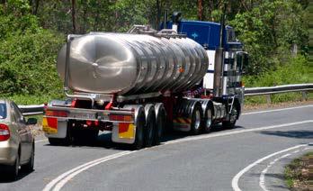
A milk tanker.
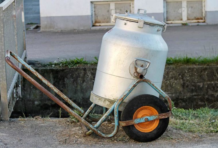
A milk container:
- may not be entirely or partly manufactured of copper or an alloy of any toxic material
- must be smoothly finished and be without any open seams, cracks or rust stains
- must be manufactured in such a way that all levels in contact with milk are reachable for washing and disinfecting purposes
- may not be used for any other purpose than for the handling of milk
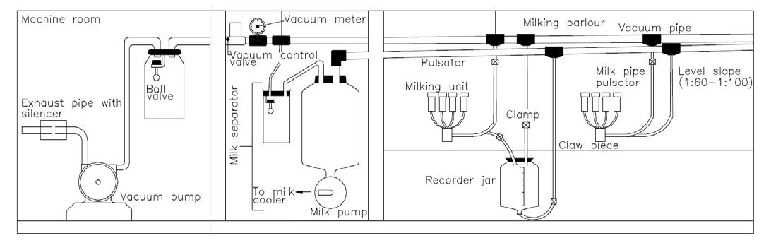
Figure 1: Schematic presentation of a milking machine system.
A milking machine must:
- be manufactured in such a way that the vacuum pipe of the machine can be drained to remove all the moisture from it
- be equipped with a mechanism by means of which the milk-flow from every milk animal is visible
- comply with the sub-regulations regarding milk containers above
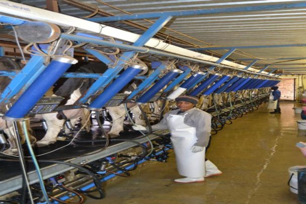
Setup of the pipelines in a milking parlour
A mass farm milk tank:
- must have a direct run-off drop to the outlet point
- must be equipped with an outlet pipe, manufactured and connected so that all moisture can run out of the tank, and the end of the outlet pipe must be provided with screw thread on which a screw top fits with which the end can be blocked
- must be equipped with a stirring device that can mix all the milk in the tank within five minutes after setting it in operation
- must be equipped with a thermometer that can indicate the temperature of the milk in such a tank to the nearest 2° C
- must be equipped to cool the milk to 5° C or lower in the tank within 3 hours and to keep the cooled milk at a temperature of between 1° C and 5° C
- may not be installed closer than 0,5 m to a roof, ceiling or wall
- must be insulated so that when cooling does not take place, the temperature of the milk in the tank will increase by no more than 3° C when the ambient temperature is 32° C
- must comply with the sub-regulation regarding milk containers
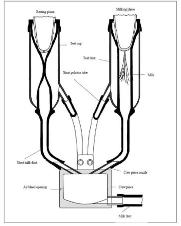
Figure 2: Presentation of milking and resting phases within the teat head.
A milk tanker must:
- be installed with a run-off slope to the outlet pipe, so that the entire contents of the tank can drain from the outlet pipe while the vehicle systemscle is in a horizontal position
- be insulated so that the temperature of the milk in the tank will rise by no more than 2° C each 48 hours
- have at least one opening with a dust-tight lid through which the inside of the tank can be inspected and must be so equipped that all surfaces that come into contact with milk can be washed and disinfected
- comply with the sub-regulation regarding milk containers
All apparatus used for heat treatment of milk must be provided with thermometers and thermostats which are accurate over the entire designated scale sequence to 0,5° C. In addition, mechanical temperature and time regulators must have a flow regulator valve and a flow diversion valve that automatically feeds back the milk to the balancing tank. The milk flowing back should not be subjected to heat treatment.
Milk containers and other loose and fixed apparatus and equipment must be washed and disinfected after use until clean, so that fats and milk residues are dissolved and removed and that the bacteriological count on the surface that comes into contact with milk does not exceed 10 bacteria per 100 mm2 of such a surface.
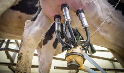
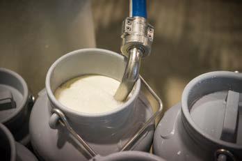
The milking unit.
Components of a general milking machine system
A milking machine system is composed of various components as seen in Figure 1.
Vacuum pump
Milk is extracted from the cow’s teats by a sucking action. The reduced pressure or sucking is obtained with the aid of a vacuum pump, which is constantly removing air from the sealed milking machine system.
Teat heads and teat shields
The sucking action is applied to the teats by means of sturdy teat heads, which envelop the elastic teat sheaths. The teat sheaths empty the milk on the underside in four milk tubes through which the milk is discharged.
Coupling
The four milk tubes are collected at the coupling, from where the milk is transported in a thicker milk tube to weighing bottles or a main milk tube. Some couplings are provided with a valve with which the vacuum on the teats can be closed after milking.
Milking unit
The four teat heads, teat sheaths and milk tubes, together with the coupling and milk tube forms the milking unit.
Pulsator
Continuous suction on the teats would obstruct the blood circulation in the teats, resulting in irritation and injury.
To prevent this, the suction effect must be interrupted periodically. The pulsator effects this action. The pulsator interrupts the vacuum effect by letting in air between the teat head and the teat sheath. This causes the distinctive rhythmical action of the milking machine, whereby blood circulation is stimulated in the teat walls. Figure 2 clearly shows the effect of the pulsator on the teat sheath and how the milk phase (vacuum) and the rest phase (air pressure) develop within the teat head.
Vacuum control valve
Conventional vacuum pumps (rotor and suction types) can reach a vacuum level much higher than what is safe for the cows. This valve keeps the prevailing vacuum level in the milking machine system constant on a fixed safe value.
Vacuum meter
The prevailing vacuum level in the system is indicated on the meter. Any variations or shortages in the system’s main vacuum supply can be observed on the meter. The correct operation of the meter is of utmost importance.
Vacuum tank
It serves as protection for the vacuum pump against the inlet of liquids such as milk, condensed water vapour or cleaning agents. It also serves as storage for a reserve vacuum and as a shock breaker against vacuum variations in the overhead vacuum supply.
Separator
The separator pumps the milk from the vacuum to atmospheric pressure. With most modern systems, this separator consists of glass bottles and a pneumatic or electrical milk pump, which also forms the power source of the circulation purifying system.
Moisture trap
This container is placed directly adjacent to the separator and forms an interposition between the main vacuum supply and the separator. Its function is to prevent condensed milk vapours from dripping from the vacuum line to the separator and contaminating the milk.
Pipelines
Extended pipelines of different materials are applied for the distribution of the vacuum to all user points, for the transport of milk to the separator, for the circulation of cleaning agents and for the provision of fresh water to the various milking points.
Published with acknowledgement to the ARC Agricultural Engineering for the use of their manuals. Visit www.arc.agric.za for more information.