
Adjustment of the rotary tiller
When working with the rotary tiller one must obtain a reasonably coarse finish. In other words, clods must be formed. This promotes moisture penetration and prevents erosion and water runoff. If the finish is very fine, the soil usually tends to puddle and wind and runoff problems develop.
There are three adjustments that can change the finish obtained by a rotary tiller, namely:
- the speed of the rotor, or blades;
- the forward speed of the tractor; and
- the position of the rear shield of the rotary tiller (see Figure 1).
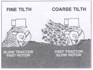
Figure 1: The desired soil finish can be achieved by adjusting the rear shield, rotor and tractor speed
Other factors can also play a role, for instance, the texture and moisture content of the soil, but the rotor can normally be adjusted for three or four different speeds. The faster the speed, the finer the finish will be and the slower the rotor speed, the coarser the finish. If, for instance, there is a lot of organic material to be worked in, the rotor speed will necessarily be faster to work all the material into the soil.
Rotor speed should be increased as soil moisture increases to keep soil moving through the rotor. Most soils, if worked too wet, will dry so hard that penetration of a good seedbed is almost impossible and plant germination and growth are severely retarded. On the other hand, working soil too dry causes excessive dust and increases blade wear.
The PTO-speed is normally 540 rpm for the small models, but for the bigger models, with a working width of up to 4,6 m, a PTO-speed of 1000 rpm is used. It is advisable to consult the users’ manual for every machine before using the machine in the fields. Rotor speeds may vary from about 140 rpm to nearly 300 rpm for extremely fine tilth.
A medium speed is generally adequate for most field conditions. The faster the forward speed of the tractor, the coarser the finish will be. If the aim, however, is to apply weed control, a faster speed will not bring about effective weed control. The forward speed of the tractor must therefore be reduced until weed control is effective. Larger blade bites mean less soil pulverization and reduced power requirements. It is best to use the slowest rotor speed and largest bite (forward speed) which will provide an acceptable tilth or degree of pulverization.
Excessive blade wear and soil friction may result if the forward speed is too fast for the rotor speed being used. As the rotor turns, the outer surface of the blade is pushed against uncut soil, causing throwing of the surface and using power (see Figure 2).
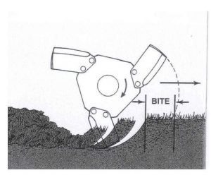
Figure 2: The blade bite is determined by the rotor and tractor speeds
When the rotor- and forward speeds are matched, a gap will be present between uncut soil in front of the rotor and the outer surface of the blades as the rotor revolves. As the operating depth increases, this clearance will gradually decrease, and the blades will be in continuous contact with undisturbed soil. If the rotor speed remains constant, the blade bites vary when the forward speed is changed.
Therefore, it is clear that slow forward travel will produce small bites and thus a fine tilth, while faster speeds will produce bigger bites by the blades and thus coarser tilths. Normal forward speeds for most rotary tillers range from 4,0 to 9,0 km/h, depending on soil conditions and desired results.
All soil, cut by the blades is carried inside the blade until it reaches the back side. The soil is then discharged, between the blades, before they reach their next cutting position and more soil is pulled in. If the soil is not discharged, the rotor will soon be blocked.
Therefore, it is clear that rotor diameter, rotor- and forward speed, blade arrangement, soil moisture and the volume of trash will have an effect on the soil movement within the rotor. Raising or lowering the soil shield, at the back, controls the amount of soil shattered as clods leave the rotor. When the shield is raised, soil cut by the blades is not broken by impact with the shield. Large clods, trash and weeds remain on the surface, and this method is recommended for tillage before the spring season when the soil will be reworked and planted.
The large clods and trash on the surface help to control erosion by wind and water. Raising the shield also reduces power requirements and lowers the tendency for damp soil to stick to the shield or plug the rotor (see Figure 3). Lowering the shield increases soil pulverization and provides a finer seedbed, incorporates trash better and helps to level the surface. Thus, for a fine tilth the shield must be lowered and select a fast rotor speed, or slow forward speed, or both (see Figure 4). For a coarse tilth the shield must be raised and a slow rotor speed selected, or a fast forward speed, or both.
-
- Figure 3: When raising the rear shield, large clods and trash will be left on the surface of the field
-
- Figure 4: When lowering the rear shield, soil pulverization increases providing a fine seedbed
Tilth produced by a rotary tiller depends on these factors:
- the soil type that cannot be controlled by the operator;
- the soil moisture than can be controlled only by delaying work or irrigation;
- the rotor speed that is easily controlled on most rotary tillers (see Figure 5);
- the forward speed that is easily controlled if sufficient power is available;
- the position of the shield that can be easily controlled;
- the number of blades per flange that is controlled by removing or adding blades (see Figure 6); and
- the amount of residue present that is controlled by removing, burning or adding more to be incorporated into the soil for the best soil condition.
-
- Figure 5: Move the lever on the gearbox and choose the rotor speed that is most suitable for the job.
-
- Figure 6: Blades can be removed or added onto a flange
Regulate the operating depth of the rotary tiller by adjusting the gauge wheels, or gauge shoes, on the machine. The links, of the three-point hitch on the tractor, must be free to float when using rotary tillers. Do not use the depth control unit on the tractor because this will cause the tiller to operate improperly.
Depending on machine design and options available, the gauge wheels may be controlled by adjusting clamps, changing pins or using crank handles. Hydraulic cylinders can also be used, especially for raising or lowering the tiller while it is in operation.
Depth control with rotary tillers is necessary otherwise the tiller will work unnecessarily deeper and deeper, with the power requirements going higher and higher.
Depth control can be achieved by the following:
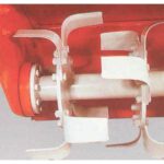
- a skid, or gauge shoe, on either side of the rotary cultivator on smaller working widths (see Figure 7);
- one depth control wheel and one skid on each side of the tiller, on wider widths (see Figure 8); and
- a depth control wheel on each side of the tiller, on the widest models.
In cases where depth control wheels are standard equipment, the depth is usually controlled hydraulically from the tractor.
-
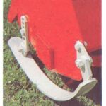
- Figure 7: A skid, or gauge shoe, can be placed on either side of the rotary tiller for depth control.
-
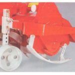
- Figure 8: One wheel, and one skid, can be placed on either side of a big rotary tiller for depth control.
We thank the ARC Agricultural Engineering in South Africa who made the information on rotary tillers available to the readers of ProagriMedia.