

The dam design in this series is limited to dams of which the maximum water depth does not exceed eight metres.
Dam outlets
The spilling of the dam must be designed and constructed in such a way that no flood damage is caused. All floodwater must be safely fed back to the original course of the river. The flood frequency for which the spillway (wet board) of irrigation dams on farms makes provision is 1 in 20 years. This implicates that there is a 5% probability that the maximum flood would be exceeded at a specific point in any year.
The spillway (total board) should be able to handle floods with a 1 in 100 years frequency with little damage.
The possibility offered by the terrain to establish a suitable and economic spillway, greatly determines whether it is practical to build the dam or not. If suitable spillway conditions are not present, it may make the construction of a dam on a specific site not economically feasible because of expensive structures.
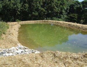
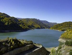
A small, but well-constructed dam outlet. Photo: Pixabay.
Spillway width, flow depth and total board
Full supply level (FSL)
This is the contour line that runs through the lowest point of the spillway, that is, it is the line that forms the brim of the water level when the water is at the point of flowing out at the spillway.
High water level (HWL)
This is the contour line at a height equal to the maximum calculated flow depth above the FSL. This is the line that forms the water level when the water flows through the spillway at the maximum design flood height.

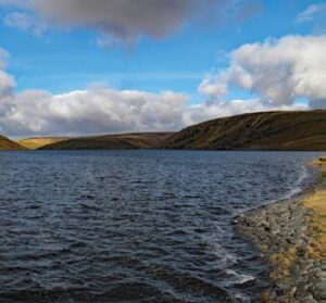
Dam waves look harmless, but pose a danger. Photo: Pixabay.
The wet freeboard or maximum flow depth (h)
This is the depth (in metres) at which water streams through the spillway when the maximum flood height for the chosen return period is experienced – it is the vertical height difference between the FSL and HWL.
Determining of outlet width (L) and the flow depth (h)
The deeper the water flows through a side spillway, the greater the flow speed will be. A critical speed exists for each type of soil, which will cause flooding if it is exceeded. The flow depth of the water through the outlet must therefore be selected so that the maximum permissible speed that is safe against erosion, is not exceeded.
The permissible velocity (v), flow depth (h) and discharge rate (m³/s) per metre width for level side spillways with different erosion hazard properties is given in Table 1.
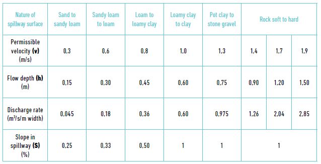
Table 1: Flow over earth dam side spillway.
The dry freeboard (H1)
The dry freeboard is the vertical difference in height between the high-water level and the crown of the wall.
The dry freeboard makes provision for three items. First, it must ensure that waves do not break over the wall at HWL. Second, an allowance of 0,15 m is made for an unreliable layer to provide for trampling by animals, unevenness and the result of frost. Third, provision is made for an additional safety factor of at least 0,3 m.
Dam waves have a very detrimental effect on dam walls over time.
Wave height:
The maximum wave height of dams of average size can be calculated with the following empirical formula:
h0 = 0,014 √K metre
where K is the length of the water in metres and h0 is the maximum wave height of trough to crown in metres.
The total freeboard (h + h1)
The dry freeboard plus the wet freeboard is called the total freeboard, that is the height difference between the FSL and the crest height of the wall after compaction.
Example:
Wet freeboard (h): Maximum flow depth: 0,60 m
Dry freeboard (h1): Wave height at HWL: 0,30 m
Plus unreliable part of wall: 0,15 m
Plus additional safety factor: 0,30 m
Therefore: Total freeboard: 1,35 m
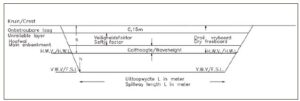
Figure 1: Spillway of a dam.
Shallow outlets are unreliable due to the possibility of blockage by debris, hail, et cetera. Rather choose a larger total freeboard than indicated in the calculations to overcome these conditions.
The following are rules for determining the minimum dry freeboard (h1) and the minimum total freeboard (h + h1):
- For catchment areas less than 2,5 km², the maximum dry freeboard must be 0,5 m and the minimum total freeboard 1,0 m.
- For catchment areas of more than 2,5 km², the minimum dry freeboard must be 0,6 m to 0,8 m and the minimum total freeboard 1,2 m.
- For dams with controlled inlets, the minimum total freeboard must be 0,6 m.
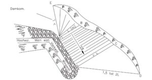
Figure 2: Plan of spillway level in the width
Shape of excavated outlets and function of wing wall
In general, an outlet excavation can be considered as a half circle with its centre against the end of the wall. Such an outlet will, however, leave the water against the rear of the wall and damage it from behind, because of the concentration of water and the forming of ditches.
The wing wall must have a length of at least the maximum downstream base width of the wall. The slope of the wing wall must be the same as that of the spillway. Circumstances, such as very erodible soil directly below the dam, may demand that the wing wall be lengthened to a suitable place where the water can be safely dispersed.
The discharged water must be taken up into the original stream without the danger of erosion.
Downstream from the line 1B to AC (figure 2), the outlet must have a drop of 1 in 100 for loamy clay to clay or soils of better quality. For spillways in soils of poorer quality, the drop must not exceed 1 in 200 to 1 in 400.
The spillway must be pegged out in such a way that the outlet width downstream of the line 1B to AC gradually becomes wider, so that the width from the point of the wing wall is at least 1½ to 2 or even more times the minimum spillway width to the end of the spillway excavation AD. It gives the spillway the shape of an inverted funnel that has the effect to distribute the water better downstream from the spillway. The area ACD is excavated and levelled.
The upward stream portion of the spillway excavation must gradually become wider from the line 1B to line 1E. This part of the excavation must stretch to at least within the full water level. The best functioning is obtained by also giving this part of the outlet a slope stream upwards.
A well-constructed wing wall. Image: Madalina Gogoasa from Pixabay.
Natural spillways
A spillway is natural if it is slightly inclined or level, perpendicular to the direction of the wing wall.
Where the natural water surface of the proposed spillway is level or has only a slight incline, it will not always be necessary to excavate the spillway. The spillway is left in its original state. The benefit is that the natural ground surface and vegetation are not disturbed, and the spillway therefore has more resistance to flooding. Trees, shrubs and bushes in such a spillway must, however, be removed, since debris can get lodged against them and reduce the capacity. The delivery of a natural spillway is calculated as shown in Figure 3:
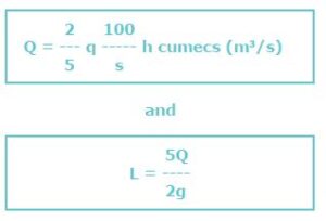
The delivery of a natural spillway is calculated as shown
Where:
q = number of cumecs (m³/s) per metre width for maximum flow depth (h) in metres (see Table 1)
s = % steepest slope
L = length in metres
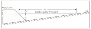
Figure 3: Natural spillway
Protection of wing walls and side slopes of spillway excavation
The spillway slopes must be paved, and the paving must be flushed with cement mortar at flow depths of more than 0,6 m. If the flow depth is more than 1 m, the wing wall must be replaced with a concrete shoulder wall.
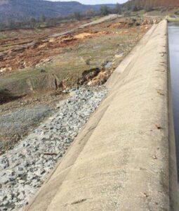
Secure your spillway properly against erosion. Photo: Commons. wikipedia.org.
Precautions against erosion after the water has left the outlet
In the design of spillways, provision must be made to prevent water from eroding the spillway. Also, ensure that erosion does not occur downstream after the water has left the spillway. It is preferred that the water is returned to the original source as soon as possible after it has left the spillway. If there is a danger of erosion, the water must be led further away to where it can be safely dispersed. This can be done by means of a canal, which is an extension of the wing wall that forms the spillway. If a donga is already present in the depression, great care must be taken with the side spillway. An expensive structure may be necessary to get the water into the donga. The construction of a dam at this particular site may be undesirable because of the cost.
To prevent undesirable concentrations of water in and downstream of the spillway, the construction of small subsurface spread walls, small barricades or the establishment of suitable vegetation may be considered.
Avoid continuous wetting of vegetation in the outlet by placing an open pipe of sufficient diameter, namely 0,15 m to 0,3 m, below the FWL through the wall, to let out a constant stream. This will keep the outlet dry, prevent the vegetation from becoming waterlogged, and ensure that the outlet floor will not wash away.
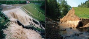
An effective outlet pipe in the dam wall will prevent vegetation from being washed away in the outlet. Photo: damfailures.org.
Economic deliberations at earth dam level spillways
At level excavated spillways, it has been found that the volume of excavated earth increases rapidly as the required width of the spillway increases. At spillways in soil, the limiting factor is the permissible flow depth that may not be exceeded. To obtain the necessary spillway capacity, the spillway width must be increased.
If the soil excavated at the spillway is suitable for the wall, and can be removed by means of the ordinary dam construction machinery, the size of the excavation will not make much of a difference to the cost of the dam. If the excavation is in hard soil, gravel or rock where breaking and blasting is necessary, the cost of the excavation may constitute a significant portion of the cost of the dam. The material removed from the spillway can be useful as a gravel layer for the wall or as paving for the wall. Where circumstances make it possible, savings can be achieved on spillway excavations by making outlets on both sides of the wall. The combined capacity of the two spillways must be equal to the maximum flood for which the dam was designed.
At spillways on sloping rock, savings can be made on the excavation by allowing a greater flow depth. This, however, requires a greater freeboard that in turn can increase the cost of the wall. The cost of the wall and the excavation must be compared, and the most economic flow depth should be determined. Savings can also be made on rock outlets by having the spillway partially over a spillway and partially by means of an excavation. In case of very hard rock, the appropriate design is usually a weir without an excavation.
Published with the acknowledgement to the ARC Agricultural Engineering for the use of their manuals. Visit www.arc.agric.za for more information.


